- HOME
-
PRODUCTS

-
ELECTRICAL PROBE SYSTEMS
- ANALYTICAL PROBE STATIONS
- BENCHTOP PROBE STATIONS
- STANDARD MINI PROBE STAGES
- SPECIALTY MINI PROBE STAGES
- WAFER CHUCKS
-
THERMAL PLATES
- BENCHTOP THERMAL PLATES
- COMPACT THERMAL PLATES
- SPECIALTY THERMAL PLATES
- HALL EFFECT MEASURMENT
- ELECTRONICS PRODUCTS
- CONTROLLERS, COOLING SYSTEMS AND ACCESSORIES
- OPTICAL EQUIPMENT
-
LIQUID CRYSTAL SYSTEMS
- ALCT SYSTEM
- LC SYSTEM ACCESSORIES
- LC MATERIALS
- CUSTOM PRODUCTS
RESOURCES ![]()
SUPPORT ![]()
ABOUT ![]()
-
-
-
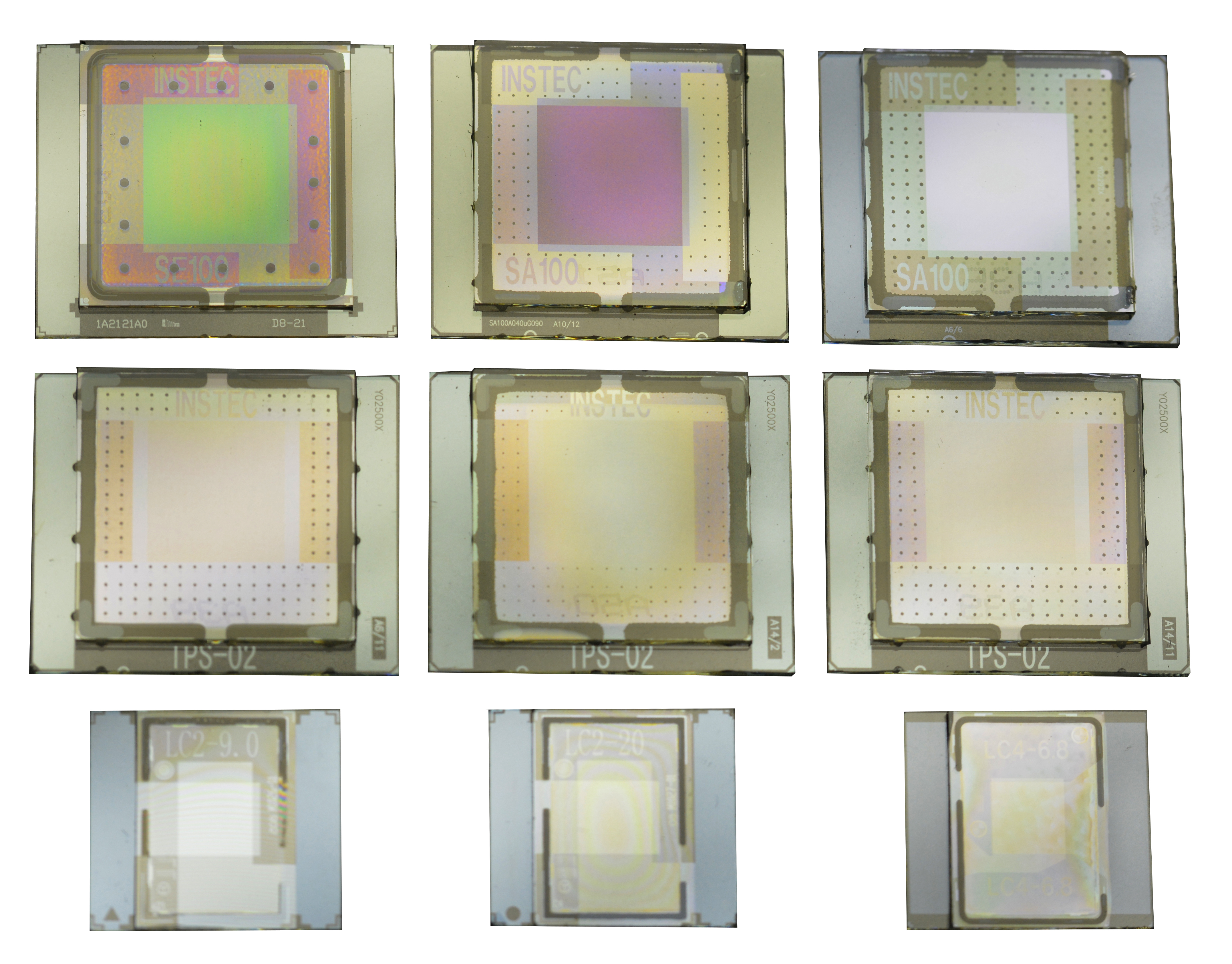
INSTEC LC Cells are sourced from various LC Cell manufacturers
Matching cell holders for easy LC testing
INSTEC offers Liquid Crystalline Materials in small quantities
Homogeneously alignment, anti-parallel, and 90° twist cells
IPS cells aligned both parallel and vertical to the electric field
Homeotropic (also known as vertically aligned) cells
ITO patterned cells with no alignment layer
Cells without PI for blue phase liquid crystals
Cells with guarding electrode to minimize parasitic capacitance
Send INSTEC a dimensioned drawing for a custom LC cell quote
LC CELLS
 PRODUCT INQUIRY
 -
-
LIST OF CURRENT AVAILABLE LC CELLS
Contact INSTEC for updates to the following list of current available LC cells.
*Each cell type comes in one box containing 50 cells; must be purchased in increments of 50 cells.
Current LC Cells in Stock [Click here]

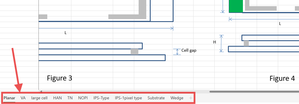
Please note that there are 10 tabs representing each of the different LC cell types and categories.
-
S-TYPE HOMOGENEOUS & HOMEOTROPIC CELLS
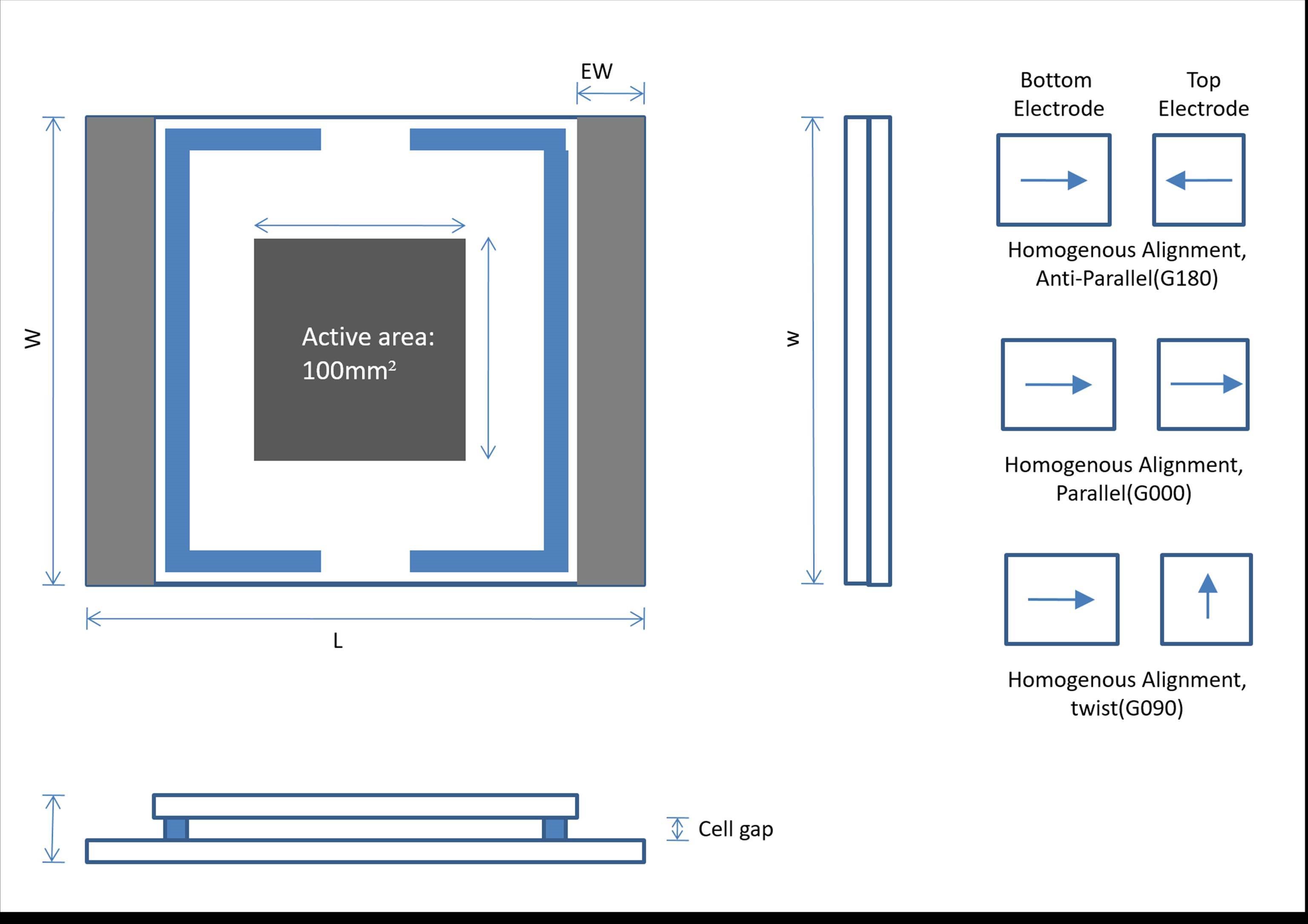
Instec stocks many different configurations of S-type cells. Specifications can be determined from the part numbers according to the following metric.
S aaa A dddu G φφφ
(1) (2) (3) (4) (5) (6)
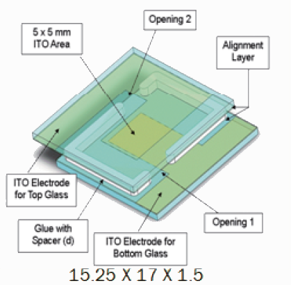
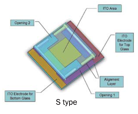
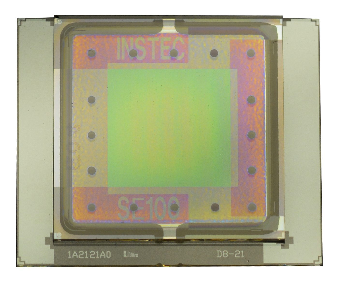
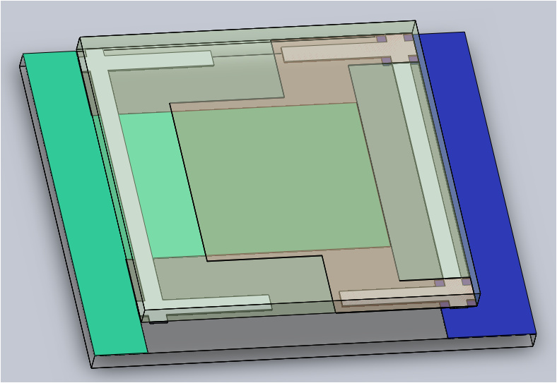
(1) Cell configuration: S means the contacts for electrodes on both the top and bottom substrate are on the bottom substrate. D means the contacts are on the same substrate as their electrode (thus one contact faces up and the other down). SGand DG mean respectively an S-type or D-type cell with an additional guarding electrode.
(2) Active ITO area in mm2: Currently, Instec has tooling for aaa=100 (10x10 mm) and 025 (5x5 mm) for S-type cells, and aaa = 256 (16x16 mm) and 400 (20x20 mm) for D-type cells.
(3) Glass type: A type cells use Soda-lime glass; T type cells use BK7 glass (TFT quality); and Q type cells use quartz.
(4) Average cell gap: dddu indicates a cell gap of dd.d μm. Instec offers cell gaps ranging from 3.3 μm up to 22 μm. Cell gaps within a batch may vary +/- 1um or 10% of dd.d, whichever is bigger. Calibrated cell gaps are available by special request with additional cost.
(5) Alignment layer: G indicates homogeneous (or planar) alignment layer, mainly for Positive NLC or FLC. Cells with a homogeneous alignment layer have a 1° to 3° pretilt angle from the plane of the substrate. T indicates homeotropic (or vertical) alignment layer. Cells with a homeotropic alignment layer have a 0° to 1° pretilt angle from the substrate normal.
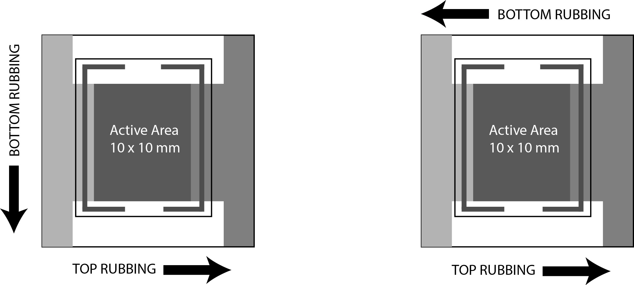
(6) Rubbing direction: φφφ specifies the rubbing angle between the bottom and top substrates. Rubbing angles of ~000 mean parallel rubbing, ~180 mean anti-parallel rubbing, and ~090 mean 90° twist rubbing. When G φφφ is replaced with NOPI, the cells have no alignment layer.
-
SG-TYPE HOMOGENEOUS & HOMEOTROPIC CELLS
Instec stocks many different configurations of SG-type cells. Specifications can be determined from the part numbers according to the following metric.
SG aaa A dddu G φφφ
(1) (2) (3) (4) (5) (6)
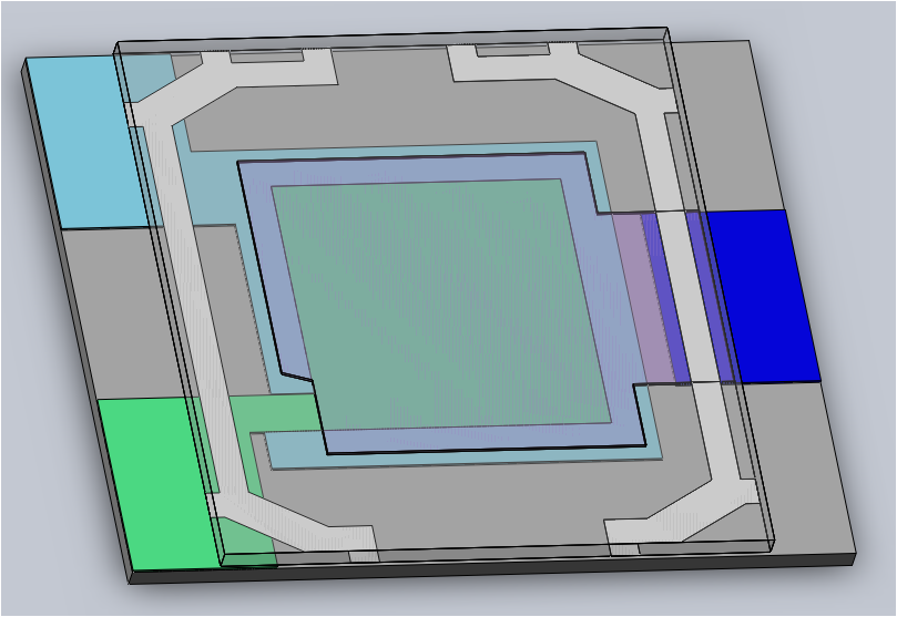
(1) Cell configuration: S means the contacts for electrodes on both the top and bottom substrate are on the bottom substrate. D means the contacts are on the same substrate as their electrode (thus one contact faces up and the other down). SG and DG mean respectively an S-type or D-type cell with an additional guarding electrode.
(2) Active ITO area in mm2: Currently, Instec has tooling for aaa=100 (10x10 mm) and 025 (5x5 mm) for S-type cells, and aaa = 256 (16x16 mm) and 400 (20x20 mm) for D-type cells.
(3) Glass type: A type cells use Soda-lime glass; T type cells use BK7 glass (TFT quality); and Q type cells use quartz.
(4) Average cell gap: dddu indicates a cell gap of dd.d μm. Instec offers cell gaps ranging from 3.3 μm up to 22 μm. Cell gaps within a batch may vary +/- 1um or 10% of dd.d, whichever is bigger. Calibrated cell gaps are available by special request with additional cost.
(5) Alignment layer: G indicates homogeneous (or planar) alignment layer, mainly for Positive NLC or FLC. Cells with a homogeneous alignment layer have a 1° to 3° pretilt angle from the plane of the substrate. T indicates homeotropic (or vertical) alignment layer. Cells with a homeotropic alignment layer have a 0° to 1° pretilt angle from the substrate normal.
(6) Rubbing direction: φφφ specifies the rubbing angle between the bottom and top substrates. Rubbing angles of ~000 mean parallel rubbing, ~180 mean anti-parallel rubbing, and ~090 mean 90° twist rubbing. When G φφφ is replaced with NOPI, the cells have no alignment layer.
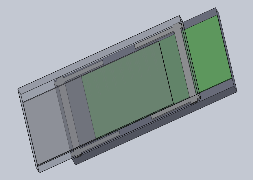
Note on usage: The guarding layer on SG type cells can be used to increase the uniformity of the electric field over the active area, reducing the effects of parasitic capacitance on electrical measurments. By connecting the guard layer to ground, the electric field over the active area better approximates an ideal parallel plate capacitor, simplifying calculations and improving measurement accuracy. Use of the guarding layer is optional, but highly recommended when performing electrical measurements on the cell. It has no significant impact on optical properties.
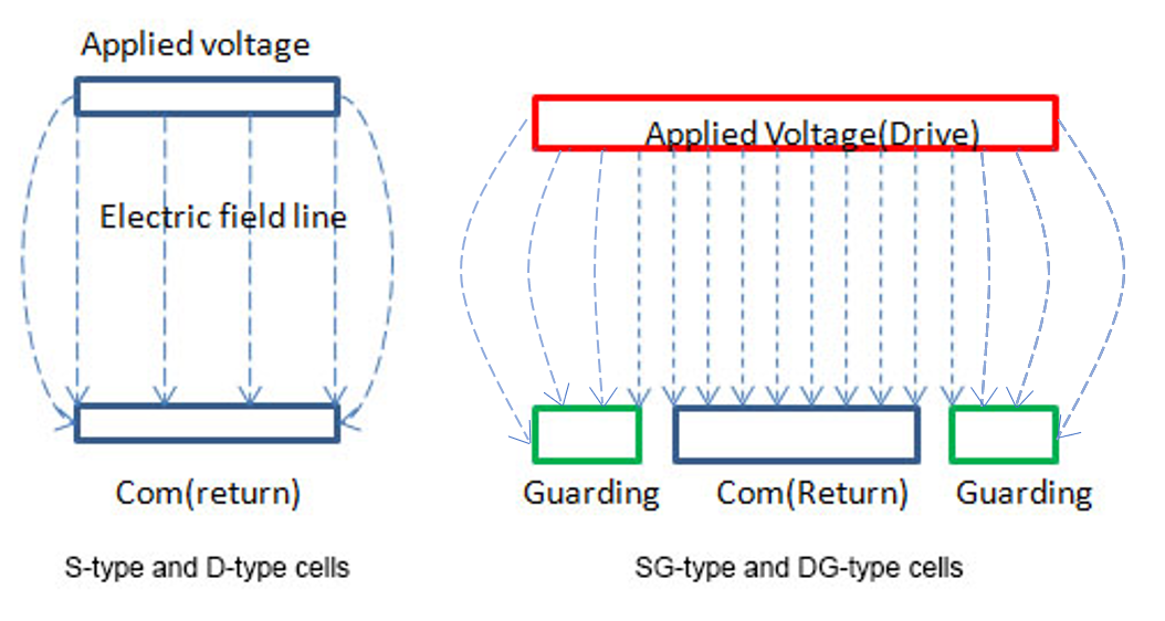
Cross-Sectional electric field diagram of standard un-guarded cell vs G-type guarded cell
-
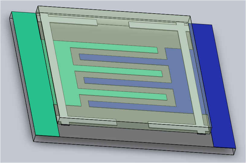
IPS IN-PLANE SWITCHING CELLS
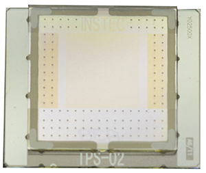
Instec stocks many different configurations of IPS cells. Specifications can be determined from the part numbers according to the following metric.
IPS w1xw2 A dddu Xφφφ
(1) (2) (3) (4) (5)
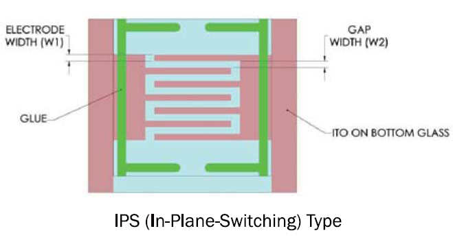
(1) Cell configuration: The in-plane switching (IPS) ITO pattern is on the bottom substrate, while the top substrate is plain glass without ITO coating. The active area is approximately 100 mm2
(2) IPS Pattern: w1 μm is the electrode width and w2 μm is the gap between electrodes.
(3) Glass type: A type cells use Soda-lime glass; T type cells use BK7 glass (TFT quality); and Q type cells use quartz.
(4) Average cell gap: dddu indicates a cell gap of dd.d μm. Instec offers cell gaps ranging from 3.3 μm up to 22 μm. Cell gaps within a batch may vary +/- 1um or 10% of dd.d, whichever is bigger. Calibrated cell gaps are available by special request with additional cost.
(5) Rubbing direction: φφφ specifies the rubbing angle between the bottom substrate and the IPS electrodes. For example, X007 means the rubbing direction is 7° from the electrode fingers (mainly for positive NLC); X083 means the rubbing direction is 83° from the electrode fingers (mainly for negative NLC). When Xφφφ is replaced with NOPI, the cells have no alignment layer.
-
D-TYPE HOMOGENEOUS & HOMEOTROPIC CELLS
Instec stocks many different configurations of D-type cells. Specifications can be determined from the part numbers according to the following metric.
S aaa A dddu G φφφ
(1) (2) (3) (4) (5) (6)
(1) Cell configuration: S means the contacts for electrodes on both the top and bottom substrate are on the bottom substrate. D means the contacts are on the same substrate as their electrode (thus one contact faces up and the other down). SG and DG mean respectively an S-type or D-type cell with an additional guarding electrode.
(2) Active ITO area in mm2: Currently, Instec has tooling for aaa=100 (10x10 mm) and 025 (5x5 mm) for S-type cells, and aaa = 256 (16x16 mm) and 400 (20x20 mm) for D-type cells.
(3) Glass type: A type cells use Soda-lime glass; T type cells use BK7 glass (TFT quality); and Q type cells use quartz.
(4) Average cell gap: dddu indicates a cell gap of dd.d μm. Instec offers cell gaps ranging from 3.3 μm up to 22 μm. Cell gaps within a batch may vary +/- 1um or 10% of dd.d, whichever is bigger. Calibrated cell gaps are available by special request with additional cost.
(5) Alignment layer: G indicates homogeneous (or planar) alignment layer, mainly for Positive NLC or FLC. Cells with a homogeneous alignment layer have a 1° to 3° pretilt angle from the plane of the substrate. T indicates homeotropic (or vertical) alignment layer. Cells with a homeotropic alignment layer have a 0° to 1° pretilt angle from the substrate normal.
(6) Rubbing direction: φφφ specifies the rubbing angle between the bottom and top substrates. Rubbing angles of ~000 mean parallel rubbing, ~180 mean anti-parallel rubbing, and ~090 mean 90° twist rubbing. When G φφφ is replaced with NOPI, the cells have no alignment layer.
-
MINIATURE STYLE LC CELLS
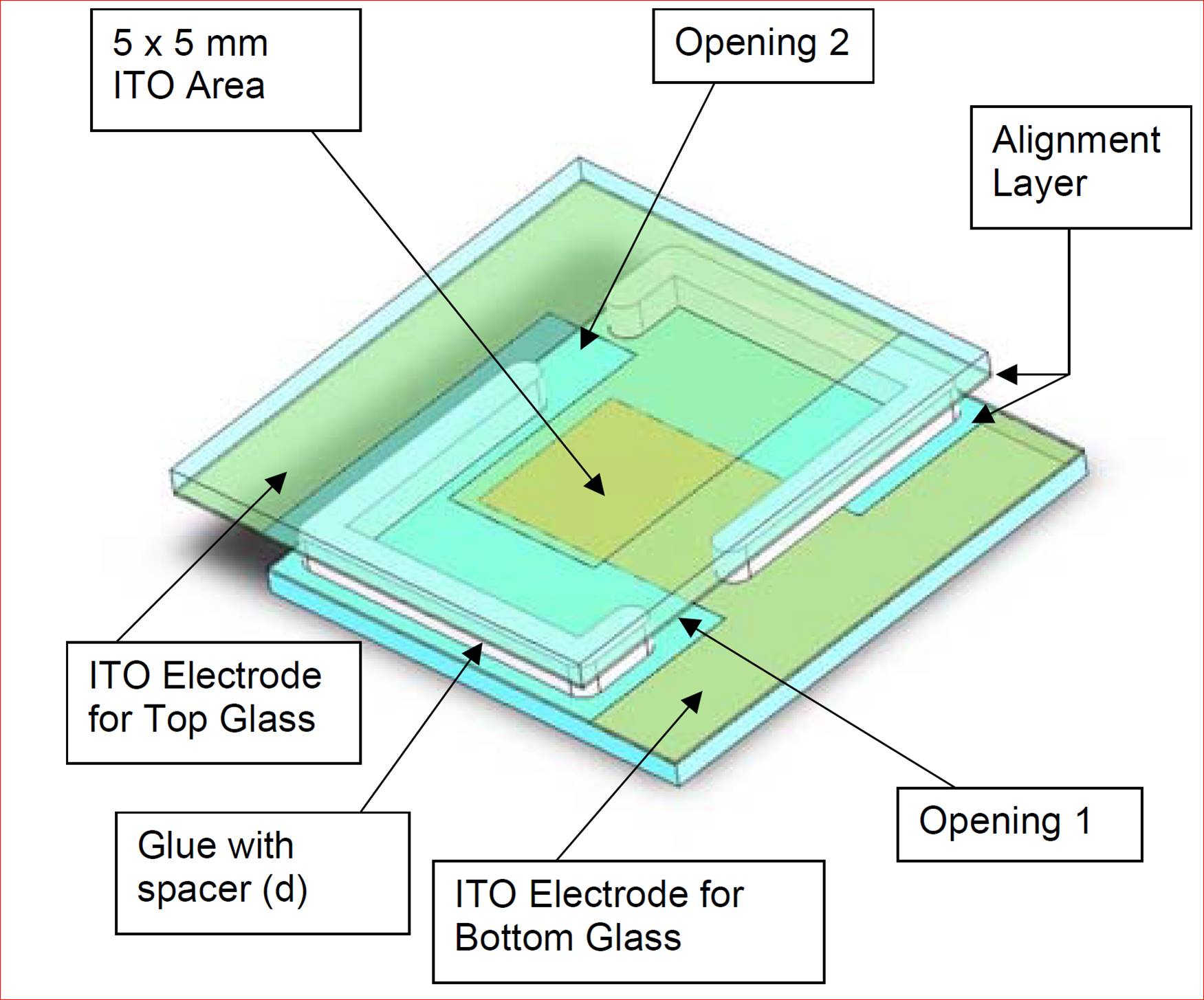
Size: 15.25 x 17 x 1.4 mm
LC2, LC3 and LC4 cells, Instec’s previous generation of homogeneous cells, are in stock with limited quantities. A list of those currently in stock can be found here.
PART NUMBER
RUBBING DIRECTION
CELL GAP
LC2-5.0
Anti-Parallel
5.0 μm
LC4-6.8
Anti-Parallel
6.8 μm
LC2-9.0
Anti-Parallel
9.0 μm
LC2-20.0
Anti-Parallel
20.0 μm
LC3-5.0
Parallel
5.0 μm
LC1-6.8
90° (twist)
6.8 μm
Old style homogeneous cells have a 1° to 3° pretilt angle from the plane of the substrate.
-
WEDGE CELLS
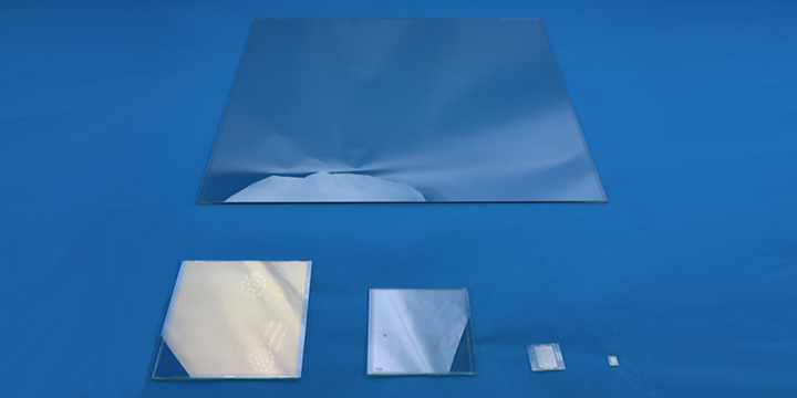
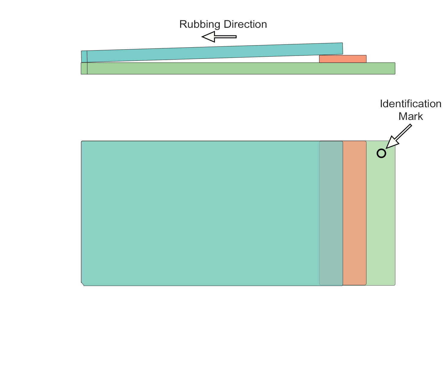
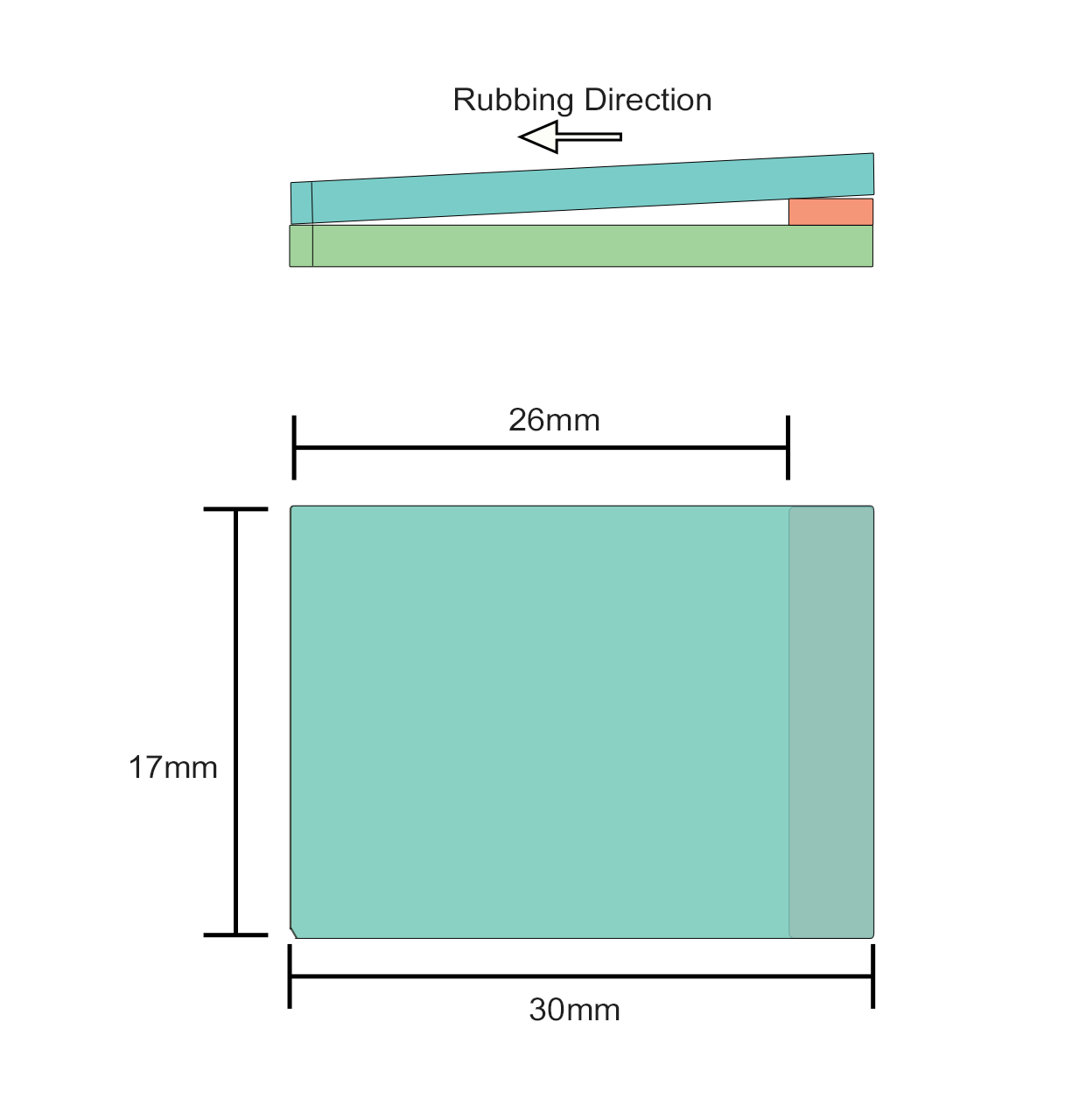
Instec carries a selection of Wedge-type cells for special applications including refractive index measurment. Instec Wedge cells are double-opening, meaning they are easily filled using capillary action. Wedge cells follow this format:
PN: 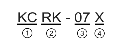

[KC] means wedge cell 
[Size] refer to table below
Mark RK RS Size 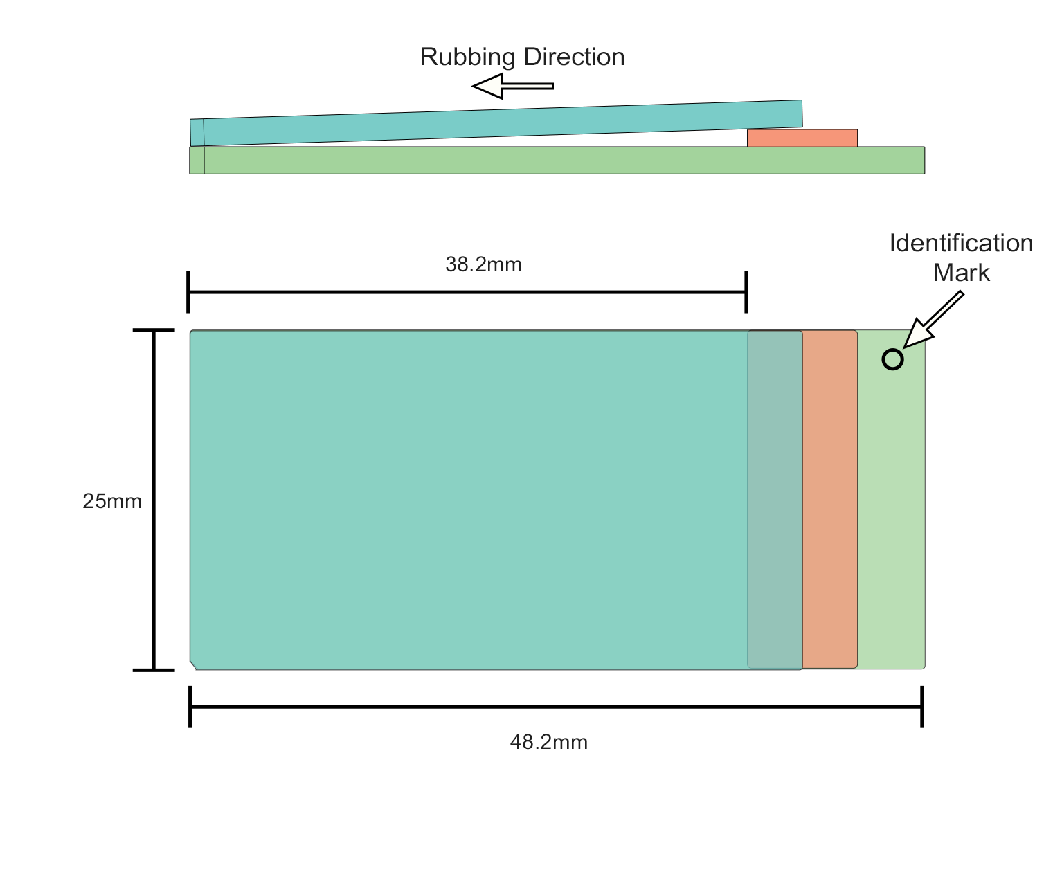

[Spacer thickness]
Mark Thickness Marking Color 03 0.3mm BLACK 05 0.5mm BLUE 07 0.7mm GREEN 11 1.1mm RED 
[X] Non-standard Options
-
Directional Film
(Contact sales@instec.com for options about coatings)
Rubbing Condition
Condition - Rotation speed, Stage speed, round-trip frequency
Direction - Arbitrary Angle
Specifications
Spec Value Polymide layer LX-1400 (Hitachi-Kasei) Film Application method Spin coating Rubbing Roll Fiber Material Polyester Rubbing Roll Fiber Length 8mm Rubbing Roll Diameter 58mm Rubbing Rotation Speed 600 Rpm Rubbing Stage Speed 30mm/scc Rubbing Round Trip Frequency 3 cycles Rubbing Direction See Diagram Above Seal Material UV Resin (Acrylic) Tan θ Calculation
Spacer Thickness Wedge Angle (Radians)
KCRK KCRS Allowance (%) 0.3mm 0.079 0.0115 +10
0.5mm 0.0131 0.0192 +8 0.7mm 0.0183 0.0269 +7 1.1mm 0.0288 0.0423 +5 
-
-
Custom Cells
Instec uses LCD production lines to make our LC cells. If you do not find what you want from the stock listing, and are interested in a custom line of LC cells, please email detailed drawings and specifications to sales@instec.com
Custom units require unique pricing considerations and will be more expensive than our standard cells. -
LC CELL HOLDERS
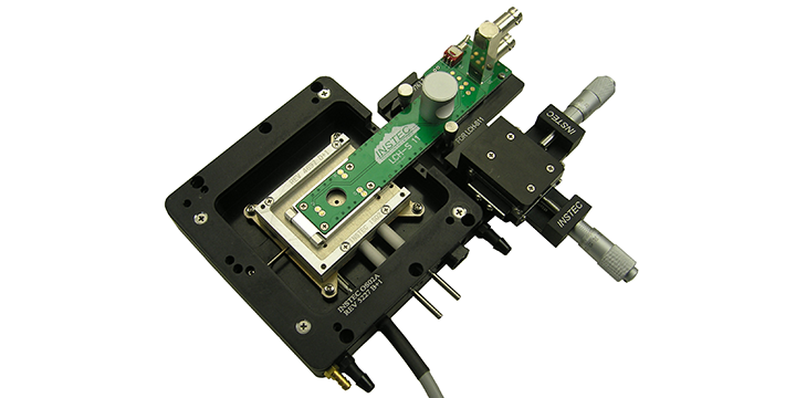
Instec LCH Liquid Crystal Cell Holders are usefull tools for conducting electrical measurments on LC cells. All LCH models are compatible with side-loading Instec thermal stages for temperature control between -196°C to 120°C (some LC materials may evaporate above 80°C). A variety of LCH models are available for different cell sizes and types.
The LCH-S11 is designed to apply electrical field to Instec's S-type, SG-type and IPS liquid crystal cells.
LCH-S12 is designed for Instec's miniature liquid crystal cells LC1 & LC2.
LCH-S9 is a simplified version of the LCH-S9 designed for use with abnormally sized, home-made or any other kind of non-Instec LC cell.
Visit our Liquid Crystal Cell Holder page for more information on different LCH models.

