- HOME
-
PRODUCTS


-
ELECTRICAL PROBE SYSTEMS
- ANALYTICAL PROBE STATIONS
- BENCHTOP PROBE STATIONS
- STANDARD MINI PROBE STAGES
- SPECIALTY MINI PROBE STAGES
- WAFER CHUCKS
-
THERMAL PLATES
- BENCHTOP THERMAL PLATES
- COMPACT THERMAL PLATES
- SPECIALTY THERMAL PLATES
- HALL EFFECT MEASURMENT
- ELECTRONICS PRODUCTS
- CONTROLLERS, COOLING SYSTEMS AND ACCESSORIES
- OPTICAL EQUIPMENT
-
LIQUID CRYSTAL SYSTEMS
- ALCT SYSTEM
- LC SYSTEM ACCESSORIES
- LC MATERIALS
- CUSTOM PRODUCTS
RESOURCES ![]()
![]()
SUPPORT ![]()
![]()
ABOUT ![]()
![]()
-
-
-
ALCT-IV1 / ALCT-IVM LC Tester for Ion Resistivity VHR RDC
Designed for LC material and display manufacturers
State of the art electronics
Measure ion density, LC resistivity, voltage holding ratio and residual DC
ALCT-IV1 / ALCT-IVM
 PRODUCT INQUIRY
 -
-
DESCRIPTION
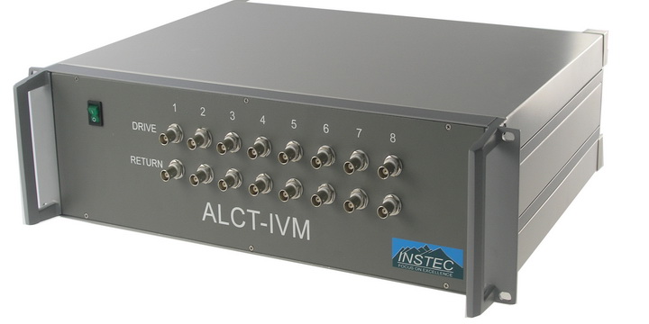
Instec designed the IV1 specifically with the industrial customer in mind. Its electronics are capable of exceedingly sensitive current measurement and low leakage voltage measurement. Its cables and connectors are triaxial in order to allow guarding against external leakages. The IV1 can be configured to measure any or all of the following:
• Ion Density
• Liquid Crystal Resistivity
• Voltage Holding Ratio (VHR)
• Residual DC (RDC)
Ion density and liquid crystal resistivity are critical components in the proper functioning of any LC display, especially active matrix LCDs. With too many contaminant ions or too low a resistivity, displays are prone to problems such as image retention and flicker. These measurements are useful to LC manufactures both in the development of liquid crystals and quality control. In addition, display manufacturers can use them for both incoming and in line quality inspection and as a diagnostic tool to trace down root causes of problems on the line.
VHR and RDC are a more direct probe for potential problems. Lowered Voltage Holding Ratios can result in noticeable flicker to a display user. Elevated Residual DC values can also produce flicker and/or image retention (or image sticking).
In measuring VHR, the IV1’s built in function generator outputs to the sample under test an AC pulse train of user adjustable frequency, amplitude, and duration. Simultaneously, the IV1’s internal electrometer senses changes in voltage on the sample, in particular the voltage droop between pulses. For the measurement of RDC, the IV1 applies a set DC voltage to the liquid crystal cell of user selectable magnitude and duration. The built in electrometer then records the residual DC voltage left on the sample cell, again for a user selectable duration. Since the duration of the initial DC voltage may be an hour or more, while the measurement time may be set to ten or more minutes, a single RDC determination can be a long process. With that in mind Instec designed the IV1’s electronics with a modular structure and options exist to add up to 8 channels.
-
SPECIFICATIONS
Ion/Resistivity
Voltage (Min)
± 10mV
Voltage (Max)
± 10V (± 100V optional)
Resolution
100μV
Frequency
0.01 ~ 1kHz
Current Range
100pA to 1mA
Current Resolution
1pA
Voltage Holding Ratio/Residual DC Voltage Measurement
Voltage (Min)
± 10mV
Voltage (Max)
± 10V
Resolution
100μV
Output Current
± 100mA (Max)
Offset Voltage
± 0.1mV
Input Capacitance (Hold Mode)
< 1pF
Leak Current (Hold Mode)
< 0.1pA
V.G Offset (Hold Mode)
± 0.1mV
Charge Injection
± 5pC

